How adaptive optics works
Follow the light through the receive telescope and beam splitter. See how the receiver path and wavefront-sensing path connect through a real-time control loop.
Sense
A wavefront sensor measures residual optical aberrations and provides real-time feedback on atmospheric distortion.
Compute
A real-time controller calculates the corrective commands required for the deformable mirror.
Correct & Repeat
The deformable mirror dynamically compensates for wavefront distortion as the closed-loop system continuously updates.
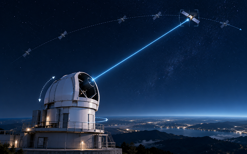
PRECISION PAT
Acquire Track Maintain the Link
High-capacity optical links require precise alignment with fast-moving satellites throughout each communication window.
OptiVeraX integrates precision Pointing, Acquisition and Tracking (PAT) for fast target acquisition, high-precision pointing, stable satellite tracking, and rapid re-acquisition.
Fast Acquisition
Rapid target acquisition at the beginning of the communication window.
Precision Tracking
High-precision tracking maintains optical alignment throughout the satellite pass.
Rapid Re-Acquisition
Designed to recover optical alignment following temporary link interruptions.
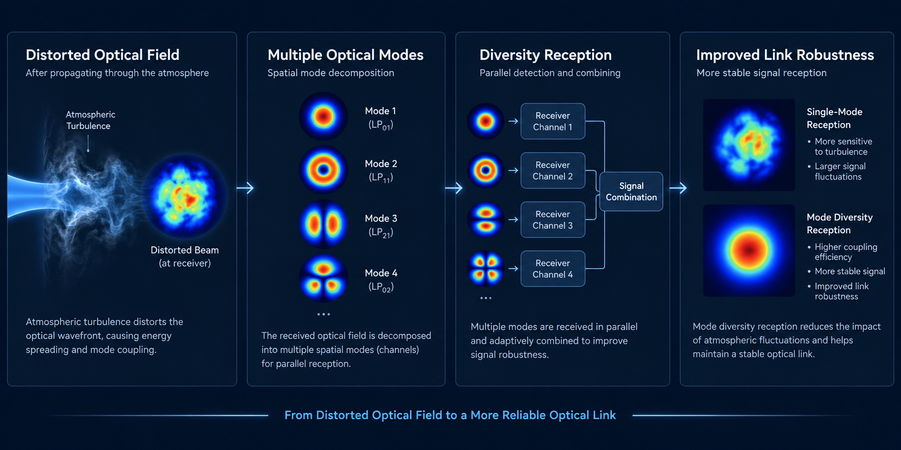
OPTICAL MODE DIVERSITY
Improving Link Robustness Under Dynamic Atmospheric Conditions
Atmospheric propagation can cause time-varying distortions in the received optical field.
Optical Mode Diversity uses multiple optical modes or channels to improve reception robustness under dynamic propagation conditions, complementing adaptive optics within the optical receive chain.
OPTICAL RECEIVER & DEMODULATION
From Optical Signal to Mission Data
High-sensitivity reception, flexible demodulation, and high-capacity data recovery for space-to-ground optical links.
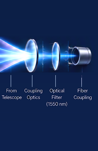
1. Optical Front End
Collect and condition the received optical signal.
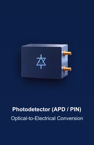
2. High-Sensitivity Detection
Convert optical signal to electrical signal.
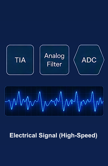
3. Signal Processing
Amplify, filter and digitize high-speed signals.
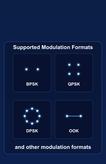
4. Demodulation
Recover data from the modulated signal.
5. Data Output
Deliver mission data to ground systems.

High-Sensitivity Reception
Designed for efficient reception of weak optical signals from space.
Flexible Demodulation
Supports multiple modulation formats for mission-specific requirements.
High-Capacity Data Recovery
Designed for high-capacity optical downlinks of up to 100 Gbps.
Optimized for Real-World Conditions
Engineered to maintain performance under dynamic atmospheric conditions.
SYSTEM ARCHITECTURE
An Integrated Optical Ground Station
From optical reception to mission data, OptiVeraX integrates key technologies into a coordinated ground-segment architecture.
Satellite
LEO Satellite
Transmits mission data via laser link (1550 nm)
Large-Aperture Optical Telescope
600 mm
Collects and focuses the incoming optical signal
Precision PAT
Acquire · Track · Maintain
Fast acquisition, high-precision pointing, stable tracking
Adaptive Optics + Mode Diversity
Real-time wavefront correction and mode diversity to mitigate atmospheric effects
Optical Receiver & Demodulation
High-sensitivity reception, signal processing and demodulation (up to 100 Gbps)
Mission Data Interface
Delivers mission data to customer systems
Central Control & NMS
Mission Planning · Orbit Prediction · Station Monitoring · Remote Operations · Multi-Station Management